
What is VSWR? Practical 5 Tips to Optimize it in RF Systems
Have you ever thought about how a small impedance mismatch can hurt your RF performance and the whole RF chain? This blog will guide you through the basics of VSWR and show you how to make it work better in your RF systems.
Table of Contents
Summary
VSWR is a way to measure how well a transmission line transmits power. A VSWR of 1:1 means that the system is perfectly matched, and higher signal reflection values mean that there are losses in the system. The most important thing to do is to make sure that power is transferred efficiently in any RF system by controlling VSWR.
What is VSWR?
VSWR stands for Voltage Standing Wave Ratio. In a transmission line, VSWR is the ratio of the standing wave’s maximum (antinode) value to its minimum (node) value. When power reaches the antenna or load any mismatch results in reflections that create standing waves. An ideal measurement of 1:1 means there’s no reflection and a sweet spot for the power transmission efficiency.
Why is VSWR Important?
In RF systems, a small impedance mismatch in the RF chain can lead to a significant reflection of power toward the source, which leads to signal degradation or in the worst case can damage the component. It’s essential to keep that VSWR as low as possible in case you’re building anything from a simple broadcast antenna or a complex 5G network. Low VSWR means, minimizing losses which leads to efficient power transfer, and better signal clarity. It also helps to extend component and equipment longevity.
How is VSWR Measured?
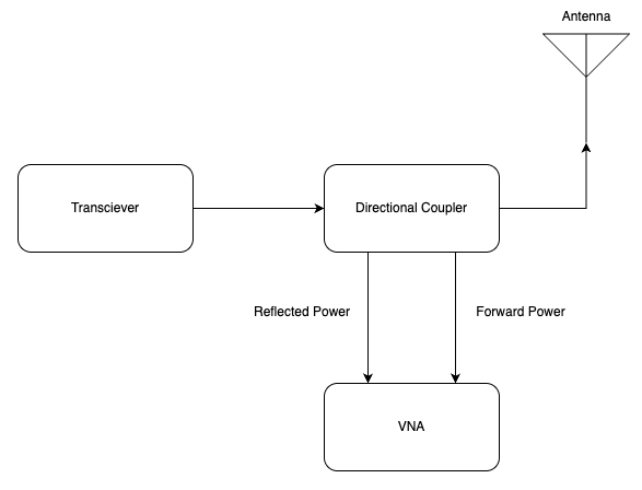
To measure the VSWR nads-on process we need a directional coupler and Vector Network Analyzer(VNA). We can measure the forward (incident) power and reflected power and compare it using this basic formula:
VSWR = (1 + |Γ|) / (1 - |Γ|)
Here, |Γ| is the reflection coefficient. It quantifies the ratio of reflected power to incident power.
For hands-on measurement of VSWR, you can:
- Connect a directional coupler at the junctions you want to measure VSWR in your transmission line.
- Record the forward and reflected power values.
- Then compute VSWR to check if your RF system has an impedance mismatch issue.
These test measurements allow you to troubleshoot and enhance RF design in real time.
How to optimize VSWR in the RF System
Optimizing VSWR in RF circuit design involves a mix of careful component selection, regular testing, and adaptive tuning. Here are several strategies that you can start using to optimize VSWR in RF systems immediately:
Proper Component Matching
Confirm that antennas, feed lines, and connectors all have compatible impedance levels.
Implement Matching Networks
Use circuits like L-networks, stub matching tuners, or baluns to fine-tune the impedance.
Regular Tool Calibration
Routinely, calibrate all measurement devices and tools to keep in shape.
Adjust for Environmental Effects
Impedance can be subtly shifted by ambient temperature, moisture, or nearby metallic objects. So, we need to take care of these effects to minimize the impact.
Systematic Troubleshooting
Isolate each and individual section of the circuit to pinpoint and correct the mismatch, when anomalies occur in the circuits.
Note: To know more about matching networks, refer to our comprehensive blog on the Antenna Matching Guide.
Practical Examples & Calculations
For example, you’re working on a new RF broadcast system project. Your measurement shows a VSWR of 2:1 which means about 33% of the transmitted power is being reflected. Then you recheck all your connections and integrate a simple matching circuit (like an L-network), which results in that ratio dropping around 1.2:1. In this way it not only improves power transfer but also shields the transmitter from potential damage.
| Measurement Point | Forward Power (W) | Reflected Power (W) | Calculated VSWR |
|---|---|---|---|
| Without Matching | 100 | 33 | ~2:1 |
| With Matching | 100 | 10 | ~1.22:1 |
Keeping detailed records for each crucial section of the RF chain like these can help you fine-tune the entire system and compare before and after results effectively.
Beyond the basics of VSWR
VSWR is only one part of the RF engineering fundamental concept. You might also consider parameters such as return loss, impedance bandwidth, and the emerging role of adaptive matching networks. These concepts also adjust matching conditions in real-time and optimize the RF performance, especially in dynamic environments. Exploring these adjacent areas will deepen your understanding and elevate your RF design approach for future challenges.
FAQs
What is a good VSWR?
A good VSWR is generally close to 1:1, which signifies the signals have a perfect impedance match. In practical scenarios, a VSWR of up to 1.5:1 is often considered excellent implying minimal reflections.
What is the meaning of VSWR 1.5:1?
A VSWR of 1.5:1 indicates that the maximum voltage in the transmission line is 1.5 times the minimum voltage. In terms of the reflection coefficient (|Γ|), it is roughly about 0.2 which is about 4% of the incident power that’s getting reflected. This level of mismatch typically falls within the acceptable limits for VSWR.
What does a high VSWR mean?
High VSWR shows a significant impedance mismatch between the transmission line and load. It also signifies that most of the transmitted power is getting reflected. It will degrade system performance, reduce efficiency, and potentially damage sensitive components like amplifiers. In many systems, a VSWR close to 3:1 is considered unacceptable and needs corrective action.
What is VSWR in VHF?
In the VHF (Very High Frequency) band, the basic principle of VSWR remains the same as other frequencies. Typically, a VSWR below 1.5:1 is ideal for VHF systems and some systems might operate reliably upto 2:1 of VSWR value.
How can I measure VSWR?
VSWR is commonly measured using VNA. By recording the forward power and reflected power on a transmission line. Then compare those power levels by using the formula VSWR = (1 + |Γ|) / (1 – |Γ|)
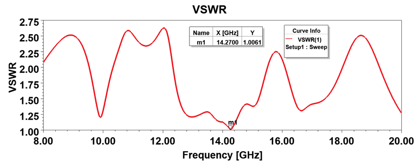
Does VSWR change with frequency?
Yes, VSWR varies with frequency. The impedance of the transmission line is frequency-dependent. So, it’s crucial to measure VSWR across the operating frequency band.
We invite you to deepen your RF engineering knowledge by exploring additional articles on RF system optimization share your thoughts in the comments, and stir up a conversation with like-minded professionals. Your insights might be the spark for someone else’s breakthrough in mastering the RF system design concept.
Важная запись, сам только что углублялся по этой теме!!!